Model Boat Mayhem

Please login or register.

Login with username, password and session length.
Pages: [1] 2   Go Down

Author Topic: Vic Smeed's River Queen  (Read 7270 times)

SailorGreg

  • Full Mayhemer
  • *****
  • Offline Offline
  • Posts: 1,326
  • Money talks - it says goodbye
  • Location: Hayling Island, Hants
Vic Smeed's River Queen
« on: March 12, 2020, 10:43:04 pm »

 Since I started building model boats I have always been impressed by those who build proper clinker model hulls, and have always assumed they have a level of skill way beyond mine.  So recently I thought I would test that assumption and have a go at Vic Smeed’s River Queen design. I bought the plans and set to, but I warn you now, this build will not end up in the Masterclass section!  I started off building a trial hull just to identify the likely issues (lots of them!), and used cheap ply for the planks, so they were never going to bend properly.  I got about a third of the way through a very messy planking, and decided it was time to start on the real thing, but I am glad I did the trial because it did indeed help me resolve some fairly fundamental issues.  This will be electric powered, not steam, in case any steam enthusiast was getting excited.

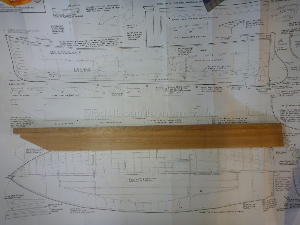
The first job is to make the building jig, and here is the backbone of it on the plan.


I also photocopied the bulkheads from the plan, and then taped the centre line onto a piece of ply, traced it, then flipped the template over to get the matching half.


The next job was building the keel/stem/deadwood which is illustrated in the next few piccies.  The various pieces were cut to rough shape from the plan and fettled to fit.  (Occasional pictures are from my trial hull, so if you spot some differences in the wood or joints, that is why.)


The stern deadwood has the prop shaft running through it so I made it in two parts, grooved them out on the router table and Araldited the whole lot together.


When doing this part on my trial hull, I discovered an error in the plan. The keel is drawn in the side view as 3/8” deep, but everywhere else as ½” deep.  The housing in the bottom of the deadwood obviously needs to be ½”, not 3/8”, as you can see from the piccie above, with the correct sized deadwood laid over the plan.

The keel is then glued to the deadwood and the first really tricky part is looming – cutting the rebate for the planks along each side of the stem/keel/deadwood.  This was one area where I made a bit of a mess on my trial hull, and was only slightly better on the real thing.  A combination of sharp Stanley knife, small chisels and abrasive paper eventually got me somewhere close. 


The hardest part was where the planking sweeps up in a curve towards the transom.  I had a practice go on a scrap of wood to make sure I could cut a smooth curve, then did it for real -


Then took a chisel to make the rebate more like |I thought is should be.


You can see that this process has exposed the tube for the prop shaft – not good for the chisel edge, and potentially annoying when putting a plank over that area.

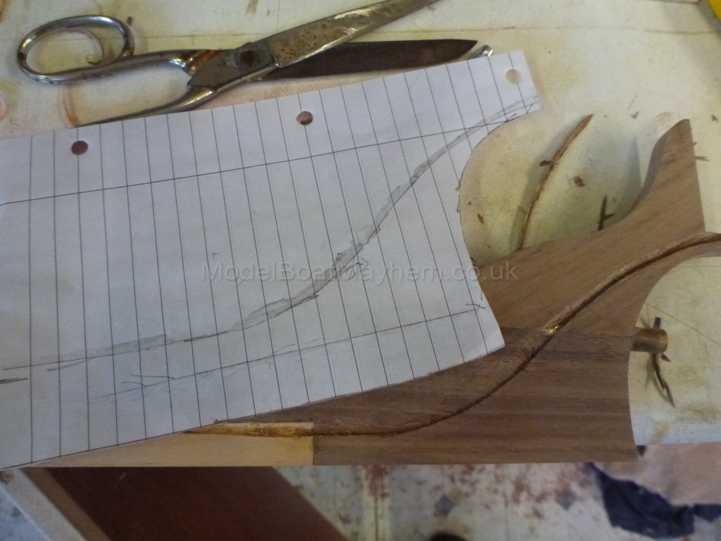
Next problem was how to reproduce that curve, cut freehand, on the other side.  I traced the curve, cut out the pattern and drew round it on the other side.


With the rebate completed on both sides (and a fresh tub of wood filler standing by for later!), it was time to set the frames and keel up on the building jig.  Most of the frames are removed after building, so were made of scrap plywood.  The transom and the frames at each end of the hull remain as part of the hull, so were made from slightly more presentable wood.  The plan suggests screwing the transom to the backbone, but this leaves a screw hole to be filled in the middle of the transom.  I added a tab to the top of the transom so I could fix it in place then cut it off once the hull was finished.


The plans show access doors in the rear bulkhead, and I cut the hole for these before fixing it in place on the jig, and made a blank to fit the hole.


Slots had been cut in the backbone to accept the frames as indicated on the plan. 


However, when they were put in place, the cutouts for the keel to sit in were all at different heights.  I had to shim all of the frames by different amounts to get them all to sit in line for the keel.  Once done, this is where we were.


Having shimmed the frames I was concerned that maybe the sheer line was going to be all wavy up and down, so I turned everything the right way up and put a flexible strip along the tops of the frames to check.  Everything looked fine.  Big sigh of relief – not sure what I would have done if it had been wonky!


Next step some planking.  Oooh-err.  {:-{ {:-{
 
Greg


Jerry C

  • Full Mayhemer
  • *****
  • Offline Offline
  • Posts: 1,504
  • Location: Caernarfon, North Wales.
Re: Vic Smeed's River Queen
« Reply #1 on: March 13, 2020, 12:42:52 am »

Way to go Greg!
Looking good so far. Ref. Your error in plan re keel and deadwood. I can’t see from pics of plan but is there a keelson  on this model?  The reason I ask is because when I built Wear I got confused because it doesn’t have one. Patternmakers’ Boat (can’t remember name) had one and a Montague whaler and my old Redwing OD had one so I thought all clinker boats had one.
When you plank up ensure you keep the planking balanced 1p, 1s 2p 2s etc. or you’ll get a kink in the jig.
For “geralding” I found a 1/4” mortise chisel scary sharp was the way to go and for top shamfer on planks a set of those toy Rolson planes also scary sharp, and a 1/2” strip of Formica invaluable for marking out.
The mistake on Wears plans was where deck planking shown butting up on inside of shear strake when it should lay over the top and end grain and joint covered by rubbing strip.
If memory served the best I managed was four planks a day.
Kind rgds
Jerry.

SailorGreg

  • Full Mayhemer
  • *****
  • Offline Offline
  • Posts: 1,326
  • Money talks - it says goodbye
  • Location: Hayling Island, Hants
Re: Vic Smeed's River Queen
« Reply #2 on: March 13, 2020, 10:25:43 am »

Thanks Jerry.  Yes, there is a keelson (if that is what the plan calls the hog, the strip that lies on top of the keel).  If you look at the picture of the deadwood over the plan, you can see there are two rebates and a dotted line on the plan that indicates the keelson/hog.  And other parts of the plan clearly show a 1/2" keel.

I am actually much more advanced than I show here.  I thought it best to make sure I had at least a 50/50 chance of finishing this before I began a build log.   ;)   But I am always happy to have your advice. I will cover my attempts at geralding in the next exciting instalment!  (And I have never done better than 2 planks a day, and mostly one!)

Greg

frazer heslop

  • Full Mayhemer
  • *****
  • Offline Offline
  • Posts: 303
  • Location: Durham
Re: Vic Smeed's River Queen
« Reply #3 on: March 13, 2020, 02:56:15 pm »

River Queen is a nice build I made my boat about 20 years ago and Im just starting to get ready to build her sister River Princess she will be a steamer
I cannot remember the problem youve had with the keel although I cannot remember what I did ast week
For the geralding I used a rabbit, rebate or shoulder plane although a good sharp chisel is just as good
Good luck
kind regards
frazer
Logged

SailorGreg

  • Full Mayhemer
  • *****
  • Offline Offline
  • Posts: 1,326
  • Money talks - it says goodbye
  • Location: Hayling Island, Hants
Re: Vic Smeed's River Queen
« Reply #4 on: March 15, 2020, 10:03:57 pm »

 Before embarking on the planking, there is a little bit of fairing to be done on the transom and bulkheads that will remain in the hull.  Here the fairing is half done.  Pencil scribbles let me know where I still need to sand.


So on to planking.  I guess many people, like me, have read descriptions of how this is done, but it’s not until you actually do it that you spot the omissions in those descriptions! I will try and fill in some of the gaps.  The first step is to mark each frame with the plank widths, that is you measure the distance from keel to sheer at each frame and divide by the number of planks (12 in this case).  OK, I can do that.


It wasn’t clear to me whether you take the measurement around the frame from the face of the keel or the bottom of the rebate, or if it matters.  I took it from the face of the keel then added a bit to the first plank to allow for the depth of rebate. 

So cut the planks to the marks and you’re done!  Wrong, because we need an overlap so the planks need to be a bit wider than that.  But how much?  The plans showed a pretty small overlap although nowhere did it actually advise what this should be.  Also, I made the mistake on my trial hull of cutting the garboard plank (the one that lies along the keel) to the marks and then adding an overlap to the next plank.  This, I realised after a lot of sketching things out, would mean I either ended up with a very wide sheer strake (plank number 12) or would be short by the width of an overlap.  You have to cut every plank to overlap the marks on the frames by 3mm and start the next plank at the mark.


The plan also calls for 1/16” ply for the planks.  This is nice and flexible but I wasn’t too confident in my ability to cut good geralds (the tapering rebate at the ends of each plank so that the bow and stern end up with flush planking – more explanation later) in 1/16” ply.  I also wondered about the robustness of a hull built of this, so I decided to go for solid timber 2.5mm thick.  (The plan is all imperial measurements, but I usually work in metric so you might find an odd mix of units appearing.)  That seemed a nice number, so I decided my overlap would also be that. In fact it turned out I needed a bit more once I started building my trial hull (to allow some wriggle room due to my poor measuring/marking), so for the real thing I opted for a generous 3mm.
Right, got that out the way.  Planking material next.  Ideally I would buy ready cut sheet out of which to cut the planks, but most of that available is only 100mm wide, which I reckoned would leave me with loads of wasted material once I had cut a curved plank out of it.  What I wanted was 2.5mm sheet about 250 or 300mm wide so that I could cut several planks from each sheet.  I quickly concluded I would need to make my own.  I also wanted a close grained wood that would steam well (as I didn’t know if I would need to steam the planks or not).  A tour of my local (only 15 miles away!) timber merchant left me with a couple of planks of beech for a good deal less money than a whole sheaf of ready cut sheets. I won’t bore you with the processing to get the sheets, suffice it to say that a bandsaw and a planer/thicknesser helped a lot!
Having scorned 1/16 ply, I actually used it a lot to cut patterns for each plank.  It is easily held in place on the hull, cuts easily and I often added bits as well as taking them away to get a good fit to all the marks on the frames and at the bow rebate.  I had a fair number of these patterns from my trial hull, although it quickly became clear that I wasn’t building an identical twin!
Here is the garboard strake being test fitted.  I did actually steam this as there is a lot of twist at both ends to get the plank lying flat in the rebate, but it turned out this was the only one I steamed. In hindsight I might have done a better job if I had steamed more of the planks.


As mentioned before, each plank has a rebate at each end, or gerald (heaven alone knows why it’s called that), to bring the planking flush at bow and stern.  I marked the 3mm overlap, then starting at about 700mm from the end of the plank I ran a sharp blade along the overlap line then used a bull nose plane to cut the Gerald. A picture or two –


Once the plank was in place I used a chisel to take Gerald down to nothing at the end.


As well as the usual clamps and clips I made up a bunch of these –


And here they are in action –


I did all my gluing with Titebond 3.  This is definitely not a job for superglue.  You do need time to get everything positioned properly.    Each plank was copied to ensure symmetry.  (As you will see later, that comment is heavily laced with irony.)


Once each plank was in place I planed a bevel the width of the overlap using this dinky little plane.  I planed it by eye, but mostly the bevels turned out pretty well and matched the next plank’s angles.


Sounds great, dead easy eh? Hmmmm –


Clearly the end of the plank was cut incorrectly or not pulled into place properly.  I fixed this by gluing a long tapered sliver of wood to cover the gap and recut the gerald to line up with the pencil mark, but it was not the only rectification job I had as the planking moved along.  But onwards and upwards! Half way there, six planks a side.


Just approaching the turn of the bilge, which caused me a few issues, but that’s for next time.


Greg


SailorGreg

  • Full Mayhemer
  • *****
  • Offline Offline
  • Posts: 1,326
  • Money talks - it says goodbye
  • Location: Hayling Island, Hants
Re: Vic Smeed's River Queen
« Reply #5 on: March 26, 2020, 01:15:02 pm »

 If you look for advice on planking a clinker hull, you may well see something like “trace the shape of the previous plank edge, add the plank width at each frame and join those points with a spline”. This, one assumes, gives you the shape of next plank to be fitted.  It sounds simple (ignoring the issue mentioned previously of the overlap) and mostly it is.  However, I found that it simply didn’t work.  In particular, at the turn of the bilge, I had great difficulty getting the planking to follow the tight curve of the frames.  I didn’t really notice the first plank to start separating from the frames, I thought after the second I could pull things back into shape, but when the third went on it was clear I was moving well away from the design.


At this point I was faced with a choice – rip off the last few planks and try again, or simply continue with planking and see where I ended up.  I didn’t really understand why I was getting this divergence, so I didn’t think re-doing it would give any significant improvement – I felt I was likely to end up in the same place.  Also, every plank was taking me quite a long time, and I was reluctant to lose all that effort.  So I carried on.  Here is the last plank going on.


It has only taken a few sentences and pictures here to go from no planks to a fully planked hull, but it was a long-winded and frustrating job for me and there were times when the whole thing nearly went in the bin.  It was also the case that as I progressed, the two sides started to become slightly different – cutting a mirror image plank didn’t work, and the two sides are not completely identical.  I fully accept that most of this was my own inexperience and lack of precision in cutting and gluing, but I am now glad I persevered, although I’m not rushing to do another one just yet!


So why did the planking not follow the frames?  (You might want to skip the next paragraph if you really aren’t interested!) I am still not sure, but I suspect I didn’t put enough curve in the planks around the turn of the bilge.  If you can imagine a plank held in the middle in its place on the hull, you would hope that, as you push the plank into place, each end meets the stem and transom in line with the previous plank.  However, if you put more curve in the plank (so the ends leave a gap to the previous plank) you have to push the ends up into place and doing this forces an inward twist into the middle section.  This twist causes the middle of the plank to follow the curve of the frame.  I think this where I went wrong, but am happy to hear other opinions.  OK, end of ramble.


With the planking completed, I took the hull off the building frame.  The two bulkheads that stay in the hull now didn’t meet the planking over most of the topsides.  Rather than try and rip them out and risk damaging the planking, I simply made new ones that fitted the hull and glued them onto the original pieces.


So now I had a hull that looked like this.


It is about 30mm wider in the beam than the design, but if you didn’t know, would it show? And because I built it, I know where the nasties are, but I will leave you to spot those as we go forward.


Next job was to stiffen the hull by fitting the inwhales.  First, the breast hook and quarter knees went in.


The inwhales were next, laminated in place with two strips of wood.  You will also spot that I have sealed the inside of the hull with some thinned epoxy, partly at least to consolidate everything and guard against failure of any of the glue joints.


Next comes the timbers, and I had fondly imagined when I was planning this that I would rivet these in place.  Indeed, I had bought a heap of 1.5 mm copper rivets for this purpose.  However, I realised that drilling the holes through the plank overlaps was going to have to be deadly accurate 100% of the time if the rivets were to end up in the right place and without damaging plank edges.  I reckoned the chances of failure were pretty high, so decided to set the rivets aside for another day. So time to dig out those venetian blind slats and fire up the steamer.  That’s for the next instalment.


Happy modelling in isolation


Greg


derekwarner

  • Full Mayhemer
  • *****
  • Offline Offline
  • Posts: 9,457
  • Location: Wollongong Australia
Re: Vic Smeed's River Queen
« Reply #6 on: March 27, 2020, 12:14:32 am »

Excellent thread of honesty and self acknowledgment....10/10........I for one, cannot see an issue with the plank at the turn of bilge....??


We have seen some excellent clinker builds on MBM that could be considered Museum Quality .,....and they are as such, however a little beyond many of our members


It would only be a Contestant Judge running a tape measure over the vessel beam & then asking you to explain where the extra 1 1/4" came from  <*< .....[need to remember Judges are still in the original Imperial world


The use of your homemade wooden C clamp bodies & tapered wedges  :-)) sure does eliminate those unsightly temporary nail holes


Looking forward to seeing your progress with staining & chosen coatings %)


Derek


PS...[we also see the use of Titebond III......which is universally accepted as the best selection for a super water resistant/waterproof glue, but any residue on a plank inside or out will react differently in surface colour and finish to that of adjoining raw wood]
Logged
Derek Warner

Honorary Secretary [Retired]
Illawarra Live Steamers Co-op
Australia
www.ils.org.au

SailorGreg

  • Full Mayhemer
  • *****
  • Offline Offline
  • Posts: 1,326
  • Money talks - it says goodbye
  • Location: Hayling Island, Hants
Re: Vic Smeed's River Queen
« Reply #7 on: March 27, 2020, 01:20:27 pm »

Thanks Derek.  I knew from the outset that this wasn't going to be a museum piece but I hope others might take heart from my rather crude efforts! 

The issue with the planks is that, from the turn of the bilge I didn't get them to lay flat gainst the frames.  In the picture you reproduce the planks should be flat against the frame you see in the lower right.  Instead there is an increasing gap as more planks are added.  But as you say, once the boat is finished and sailing, who is to say what the beam should be?  :}

Greg

SailorGreg

  • Full Mayhemer
  • *****
  • Offline Offline
  • Posts: 1,326
  • Money talks - it says goodbye
  • Location: Hayling Island, Hants
Re: Vic Smeed's River Queen
« Reply #8 on: April 09, 2020, 01:10:55 pm »

 The next stage is making and installing the ribs (or timbers as they are referred to on the plan – but I prefer ribs).  I had some venetian blind slats left over from shortening a blind, and after the recommendations on this site about their suitability for model pieces, I thought I would give them a go.  First job was to sand off the paint, then I sliced a few up on the band saw –


and planed them down to give a finished edge.  I made up a jig of slat pieces to give me a consistent width when planing.  Hope this is clear from the pic –


This left me with a large number of blanks for the ribs which I knew were going to need steaming to follow the curves of the hull.  My steamer is an old deep fat fryer with different lids depending on the size and shape of what needs steaming.  The ribs are fairly short so I put a batch of five or so into a shallow tray with holes – here it is with the cover off, sorry about the steamed up lens!


When each batch was nice and soft (several minutes, 7 or 8 from memory), I pushed them into place and clamped the top to hold them there as they cooled and dried.  They all went into place nicely, bar a couple that snapped.  Possibly a flaw in the wood, as others in the same batch bent without trouble.  Always prepare a few spare bits to guard against the odd failure.  But I can endorse the use of venetian blind slats - very useful raw material!


When they had all dried, they retained most of the shape, although there was a degree of spring back in all of them.


I then glued them all in place, and I thought the end result didn’t look too bad –


This was actually the point where I decided not to go for the copper rivets, as I couldn't see how to drill accurately - if I drill from the outside, I could easily miss the middle of the rib, and if I drill from the inside, I might emerge right on the edge of the outer plank.  Too many risks for me.  So now we move on the floors that support the floorboards.  These need to match the curve of the lower hull, and the first stage is to cut a piece of card to the rough shape, then run a pencil along a handy rib to get the exact shape.


This shape was transferred to a piece of thin ply to fine tune the final shape, as the card is a bit too floppy to give me confidence in the shape –


And once I was happy with that, I cut the actual floor piece –


As I added the floors, I made sure that they were all at the same height – wouldn’t want anyone tripping over an uneven floorboard!


Then I added the stringers on the inside of the hull that support the benches.  Simply measured from the plans and glued in place, although I did chamfer the top so that it was a level surface all the way round, as the stringer tilts slightly as the flare of the hull changes.


And that’s it for now.  Next will be furnishing the inside including fitting the motor and electrics.


Happy isolated modelling folks.


Greg
 

radiojoe

  • Full Mayhemer
  • *****
  • Offline Offline
  • Posts: 2,376
  • Location: Gosport , Hampshire , England
Re: Vic Smeed's River Queen
« Reply #9 on: April 09, 2020, 03:05:28 pm »


That's superb Greg, having worked in the boat building industry for many years I love to see traditional methods being used, I'll say this for you though you've got more patience than I've got  O0 as it's electric I assume you will have a "engine" box over the motor, Nice one Greg.  :-))


Regards   Joe.
Logged

SailorGreg

  • Full Mayhemer
  • *****
  • Offline Offline
  • Posts: 1,326
  • Money talks - it says goodbye
  • Location: Hayling Island, Hants
Re: Vic Smeed's River Queen
« Reply #10 on: April 10, 2020, 08:34:07 am »

Thanks Joe. Yes, there is an engine box, I think that will appear in the next post. And I hope we will get to see your Huntsman build, nice to see you back in boats!  :-))


Greg

radiojoe

  • Full Mayhemer
  • *****
  • Offline Offline
  • Posts: 2,376
  • Location: Gosport , Hampshire , England
Re: Vic Smeed's River Queen
« Reply #11 on: April 10, 2020, 02:22:33 pm »


Hi Greg, Yes I will do a build log on the Huntsman, it keeps me focused and you end up with a portfolio of photo's to remind me of how I did things,  not that my memories bad or any thing, now what was I talking about  %%   {-) anyway that hull of yours looks quite big from the rule in the photo I'm guessing around 30" looking forward to see how you do the running gear.


Stay well .  Joe
Logged

SailorGreg

  • Full Mayhemer
  • *****
  • Offline Offline
  • Posts: 1,326
  • Money talks - it says goodbye
  • Location: Hayling Island, Hants
Re: Vic Smeed's River Queen
« Reply #12 on: April 14, 2020, 02:08:15 pm »

Good guess Joe - 34.5" long.


Now is the time to start furnishing the bare hull.  First, get the motor positioned properly.  I cut away part of one of the floors to let me place a mounting plate at the correct height and angle.


I followed the plans for the other furniture.  Here are the aft benches being built.  Lots of cardboard cutting to make templates, then the various pieces cut out of the same stuff the planks were made from.


I also started planning where the electrics would sit.  A steam plant is a lovely thing to behold,  O0 but an electric motor, ESC and modern battery pack are not the most visually exciting things,  {:-{ so I wanted them hidden away. 


I then mocked up an engine casing over the motor.


Then made it in wood with a little shelf to take the ESC.


I realised that I would need the casing removable to get at the prop shaft joint, so the casing is held in place with a small peg at one end (just to the right of the prop tube) –


And a tab that screws into a block in the hull at the forward end –


More card templates and the benches and floorboards start to appear.


I also needed to add the capping strip over the planking edge and inwhales.  To pre-bend the strip, I made up a jig that replicated the curve of the hull and set the two capping pieces in it (although the hull was not fully symmetrical over much of the planking, it turned out that the top of the hull was, so I only needed a single jig – yippee!  :-)) ).  I did this just before going on hols for a couple of weeks (this was a little while ago now – remember when we could go where we wanted, and actually touch other people?).  I hoped that being left like this for two weeks would set the bend into the strips. 


When I got home, I took the strips out of the jig, and they promptly sprung straight again.   :(( Oh well, out with the steamer.  Steamed and put back in the jig, the strips now held the curve much better and were glued in place to finish off the edges of the hull.


The next step was to glue a rubbing strip around the outside of the hull.  This is a simple 3mm (or probably 1/8”) square section that has the edges rounded over once it’s glued in place. 


As you can never have too many clamps, I used some modified clothes pegs – I think I saw this tip here on Mayhem, but I can’t really remember – if it was yours, thanks!  A few minutes with the disc sander and you have these -


Returning to the electrics for a bit, I wanted to have a fixed point to connect the battery to, rather than a wandering lead tucked away in the bottom of the hull.  I made up a lead to sit between the battery and the ESC, and glued one end into a semi-bulkhead set inside the aft bench.  This means the ESC can remain connected to the lead in the bowels of the hull but I can connect the battery just by lifting the bench top.


I do hope you are all staying well and not going mad in isolation.  At least we have a hobby that keeps us engaged and doesn’t take us outside.  Unless, of course, you want to actually sail your boats as well as build them!  :embarrassed: Oh well, the time will surely come for that.  Happy building folks!


Greg
 

radiojoe

  • Full Mayhemer
  • *****
  • Offline Offline
  • Posts: 2,376
  • Location: Gosport , Hampshire , England
Re: Vic Smeed's River Queen
« Reply #13 on: April 14, 2020, 03:05:47 pm »


Nice Greg, I was wondering how you were going to hide the running gear in an open hull and you've certainly done that well.  :-))


Joe
Logged

derekwarner

  • Full Mayhemer
  • *****
  • Offline Offline
  • Posts: 9,457
  • Location: Wollongong Australia
Re: Vic Smeed's River Queen
« Reply #14 on: April 15, 2020, 12:03:02 am »

Hard to tell from the photographs Greg, but have you [or will you] coat the internals with of Z-Poxy or similar?......


Model boat builder over here [OZ] used Z-Poxy and then low temperature heat from a hair dryer to pre dry between each frame and gently rolling the hull during the process........worked perfectly...no concentrated depth at lowest sections etc


Those stringer shavings/planings under the motor frame  :-)) look just like a full sized boatyard..... {-)


Derek
Logged
Derek Warner

Honorary Secretary [Retired]
Illawarra Live Steamers Co-op
Australia
www.ils.org.au

SailorGreg

  • Full Mayhemer
  • *****
  • Offline Offline
  • Posts: 1,326
  • Money talks - it says goodbye
  • Location: Hayling Island, Hants
Re: Vic Smeed's River Queen
« Reply #15 on: April 15, 2020, 01:45:29 pm »

Yes Derek, the inside (and the outside) are coated with slightly thinned epoxy.  I coated the inside before fitting the ribs, and coated the lower face of each rib with epoxy as I glued them in, so there shouldn't be any bare wood hiding out of sight.  Apart from waterproofing the wood, the epoxy coats also consolidate the whole structure, so any slightly dodgy glued joints have a bit of backup.

Greg

SailorGreg

  • Full Mayhemer
  • *****
  • Offline Offline
  • Posts: 1,326
  • Money talks - it says goodbye
  • Location: Hayling Island, Hants
Re: Vic Smeed's River Queen
« Reply #16 on: April 21, 2020, 04:52:03 pm »

 And to keep Derek happy, here’s the hull with a coat of epoxy on the outside.  :}


Now we come to the decks.  The plans are a little ambivalent about how to do this.  I knew I wanted the rear deck removable, as this is where the steering servo is placed –


and we all know what happens to servos that are hidden inside the hull, don’t we?   >>:-(   I also pondered whether to have the forward deck removable in case any maintenance was needed in the bow.  The approach I took was to build a removable frame in situ for both decks –


then plank the frames off the boat.  I fitted the Samson post into the foredeck frame before decking began.


The planking is Douglas fir with black paper strips glued between to represent the caulking.  Here are the two decks nearly finished. 


You can see that both decks are missing the final little corners of decking, which need to be fixed to the boat as there is no frame in the corners. In the end, I glued the foredeck in place and hope I don’t live to regret it!  Once the foredeck is in place, the next bit is the nosings (as the plan calls them, I know no better, so nosings they are.)  These are the upstands that run along the edge of the foredeck and incorporate a fairlead for mooring warps.  The plan proposes 1/16” ply for these, but that seemed to me a bit flimsy for something that is exposed to knocks and poking fingers, so I shaped some solid timber to fit.  First I traced the curve of the foredeck edge and cut a pattern.


This was transferred to a suitable scrap of wood, and this was sanded to shape.


And that seemed to fit pretty well –


Much to my surprise, the sanded bit fitted both sides equally well,  :o :o so I cut it in half lengthwise to give me two pieces.  Then it took a little drilling, filing, sanding and fettling to give me a finished nosing.


And then I fitted the missing corners to both decks


Next in line was the rudder (although in reality I had been doing this in parallel with the decking).  The rudder is a wooden shape with cheeks glued on.  The plans show a simple straight tiller, but I fancied something a little more elegant, so laminated a curved one over a piece of wood with the appropriate curve cut in it. 


(The tiller shown in the photo is not the final version, but it does show how I made it.)


The pintles and gudgeons (or the hinges, the pintle is the piece with the pin, the gudgeon the piece with the hole that takes the pin) for the rudder have to be made, and initially I was going to follow the plans and bend them out of thin brass sheet with soldered pins, but then I remembered my little stock of 3 pin plug remnants.  A little thought and a scour through my collection of brass tube and rod, and I had a solution which was both easier and more robust.  First, I drilled out the hole for the wire in the electrical pins to 4mm.  This is a sliding fit for 5/32” tube.  I soft soldered some of this tube into each hole, feeding the solder in through the screw hole in the side.  (I used a pencil gas torch for this as the pins are a big chunk of heatsink for my soldering iron.) A 1/8” tube is a sliding fit in the 5/32” and this was to be the pintles.


A pintle for the rudder was then made by soldering a piece of 1/8” tube inside the 5/32”.


The bottom gudgeon on the rudder needs a pintle to sit on, and this was provided with a strip of brass set into the keel and a piece of the 1/8” tube soldered in place.


And when added to the rudder they look like this.  You can see that the bottom gudgeon is pinned into the bottom of the rudder for extra strength.


The transom was marked up for a hole to take the upper gudgeon – couldn’t quite decide on the transom centreline, but I think I got a happy medium!


A piece of brass angle was then cut about and glued in place to provide a steering horn.


The finished rudder and tiller –


Phew! That’s a bit of a marathon.  Hope you’re still with me!  More on the internal furniture next time, and maybe a coat of paint or two.  Stay sane, stay safe!


Greg


frazer heslop

  • Full Mayhemer
  • *****
  • Offline Offline
  • Posts: 303
  • Location: Durham
Re: Vic Smeed's River Queen
« Reply #17 on: April 21, 2020, 07:16:38 pm »

Looking very nice I think those deck ideas may well get pinched
If its any consolation Im on with her smaller sister and having the same problem getting the planks to keep on the formers
It all seems to go awry around plank 7 to 8 ho hum at least my tiddler is going to be painted
Iv built many plank on frame hulls and never struggled like this
Cheers
frazer
Logged

radiojoe

  • Full Mayhemer
  • *****
  • Offline Offline
  • Posts: 2,376
  • Location: Gosport , Hampshire , England
Re: Vic Smeed's River Queen
« Reply #18 on: April 21, 2020, 07:31:24 pm »


Hi Greg,  beautiful work on the rudder, just love those pintles and gudgeons oh arr me dear and other Cornish quotes  %%   :-))
Joe.
Logged

derekwarner

  • Full Mayhemer
  • *****
  • Offline Offline
  • Posts: 9,457
  • Location: Wollongong Australia
Re: Vic Smeed's River Queen
« Reply #19 on: April 21, 2020, 11:07:52 pm »

Watching on Greg.....great work & progress  :-)) ............ Derek
Logged
Derek Warner

Honorary Secretary [Retired]
Illawarra Live Steamers Co-op
Australia
www.ils.org.au

SailorGreg

  • Full Mayhemer
  • *****
  • Offline Offline
  • Posts: 1,326
  • Money talks - it says goodbye
  • Location: Hayling Island, Hants
Re: Vic Smeed's River Queen
« Reply #20 on: April 24, 2020, 06:50:20 pm »

Looking very nice I think those deck ideas may well get pinched
If its any consolation Im on with her smaller sister and having the same problem getting the planks to keep on the formers
It all seems to go awry around plank 7 to 8 ho hum at least my tiddler is going to be painted
Iv built many plank on frame hulls and never struggled like this
Cheers
frazer

Thanks Frazer, at least it's not just me who couldn't get the run of the planks right.  Although if you can't figure out why the planks won't behave with your experience, I'm not sure how we do it right next time (if there is a next time!). Have you taken any planks off to have a second go or are you just pressing on as I did?  And I am also painting mine - way too many bodges to allow public viewing!  %)

Greg

frazer heslop

  • Full Mayhemer
  • *****
  • Offline Offline
  • Posts: 303
  • Location: Durham
Re: Vic Smeed's River Queen
« Reply #21 on: April 24, 2020, 07:08:04 pm »

Iv remade plank 6 and reduced the last removable formers upper section by 6mm now onto the last planks but its still tryng its best to come away from the formers 1 to3. Some of the planks looked like bad fingers a visit from a sharp chisel has helped
I think if there is a solution it would be more planks say 14 or 16
When Iv looked at my old River Queen I used 14 planks as Vic Smeed mentions in his original write up .On a brighter note he did wish builders good luck getting the planking done so he may have known as the comment seems a bit tongue in cheek
Hind sight is a wonderful thing but so would  a good memory or a bit of  sense.
An old friend who built Queen at the same time as I built my version also had planking problems at the time I couldnt see why Ho Homm  all good fun. He must have used 12 planks
cheers

Logged

SailorGreg

  • Full Mayhemer
  • *****
  • Offline Offline
  • Posts: 1,326
  • Money talks - it says goodbye
  • Location: Hayling Island, Hants
Re: Vic Smeed's River Queen
« Reply #22 on: May 01, 2020, 03:53:47 pm »

 Finishing off the internals, I painted the floorboards in grey primer to represent a grey non-slip coating, and stained the tops of the seats mahogany.


I fitted the rear doors with a couple of little hinges I bought at a club bring and buy at Christmas.  The fixings are the copper rivets I originally bought to rivet the hull.


You can also see the capping piece I put over the end of the deck planks, repeated for the foredeck.  I also mocked up a gear stick from a piece of brass rod, a plastic bead and some filler to give a domed top.


Then it was time to turn the hull over and do some tedious rubbing down before masking off the gunwale rubbing strip and transom, and applying a few coats of primer.


I then sketched in the waterline by the traditional method –


The underwater part is sprayed white up to the waterline without masking off.  This leaves a feather edge rather than the small ridge produced by masking tape, so one less issue to deal with when finishing the hull.  I remarked the waterline on the white paint and set about masking off for the topsides paint.  I had been wary of this bit, wondering how the masking tape would manage the transitions over the plank edges, but the inherent stretchiness of the tape made this not too difficult. 


At least, it seemed easy at the time, but it later transpired I hadn’t been quite careful enough – but that’s for later. On with the topsides blue -


Off with the masking, and the finished colour scheme –


It transpired that I had a fair bit of paint creep under the masking, and a patch of overspray where I obviously hadn’t sealed the newspaper edge properly, but all that is recoverable with some judicious polishing once the paint has hardened properly.  A couple of coats of Halfords lacquer on the wooden parts, some dark grey on the fronts of the benches and we are pretty well there.  The proud owner could now take the tiller -


Looking at the photos, the capping strips on the deck edges which I left natural beech look a bit incongruous.  I think I will rub them down and stain them mahogany as well, another little job when I come to fettle the paintwork. 
So apart from the titivating that is it.  Obviously a maiden voyage will have to wait for better times, but I did a test tank run to make sure everything worked as it should.  It all worked well, and the excellent Prop Shop propeller churned up the bath water nicely.  I also left the boat floating for an hour or so and not a drip of water inboard.  I used my usual technique of a squidge of waterproof grease up the prop shaft tube before inserting the shaft.  Here is the boat getting wet for the very first time.


It needed a little ballast under the front bench to get the waterline level.  It still floats a little high, but as it was designed to take a steam plant and the associated weight, that’s not really surprising. Overall, an interesting project for me, and a lot of learning along the way.  I set out on this build with more curiosity than anything else, to see how I got on with a technique I had never done before. It is far from perfect but I find viewing in a darkened room and from a fair distance allows me to indulge in a brief moment of satisfaction that I got to the end.  I hope you enjoyed following along, and maybe fancy having a go yourself.  Go on. You know you want to!


Happy modelling and stay safe


Greg
 

radiojoe

  • Full Mayhemer
  • *****
  • Offline Offline
  • Posts: 2,376
  • Location: Gosport , Hampshire , England
Re: Vic Smeed's River Queen
« Reply #23 on: May 01, 2020, 04:39:40 pm »


Wow you have been busy Greg, that looks just gorgeous mate.  :-))


Joe.
Logged

SailorGreg

  • Full Mayhemer
  • *****
  • Offline Offline
  • Posts: 1,326
  • Money talks - it says goodbye
  • Location: Hayling Island, Hants
Re: Vic Smeed's River Queen
« Reply #24 on: May 01, 2020, 05:22:38 pm »

Thanks Joe, very generous (or perhaps your glasses need checking? :} ).  And it all seems to have got finished in a sudden rush - it's strange, you're building away, day after day and suddenly there's no more bits to make and only the painting to do.  And of course we all have a bit of spare time at the moment  {:-{ {:-{ .
Greg
Pages: [1] 2   Go Up
 

Page created in 0.121 seconds with 21 queries.