Table of Contents
Advertisement
Available languages
Available languages
To learn more about DELTA MACHINERY
visit our website at: www.deltamachinery.com.
For Parts, Service, Warranty or other Assistance,
1-800-223-7278 (
please call
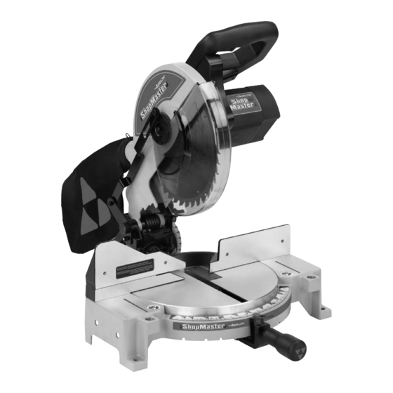
10" Compound
Power Miter Saw
(Model SM100M)
1-800-463-3582).
In Canada call
Part No. 90513776 1-07
Copyright © 2007 Delta Machinery
ESPAÑOL: PÁGINA 23
FRANÇAIS: PAGE 38
Advertisement
Table of Contents

Related Manuals for Delta 90513776


Summary of Contents for Delta 90513776
- Page 1 To learn more about DELTA MACHINERY visit our website at: www.deltamachinery.com. For Parts, Service, Warranty or other Assistance, 1-800-223-7278 ( please call 10" Compound Power Miter Saw (Model SM100M) Copyright © 2007 Delta Machinery ESPAÑOL: PÁGINA 23 FRANÇAIS: PAGE 38 1-800-463-3582).
-
Page 2: Table Of Contents
NOT be modified and/or used for any application other than for which it was designed. If you have any questions relative to its application DO NOT use the product until you have written Delta Machinery and we have advised you. - Page 3 ALWAYS TIGHTEN ADJUSTMENT KNOBS BEFORE USE. DO NOT PERFORM ANY OPERATION FREEHAND. NEVER REACH IN BACK OF SAW BLADE. NEVER CROSS ARMS IN FRONT OF BLADE. TURN OFF TOOL AND WAIT FOR SAW BLADE TO STOP BEFORE MOVING WORKPIECE, CHANGING SETTINGS OR MOVING HANDS. DISCONNECT POWER BEFORE CHANGING BLADE OR SERVICING.
-
Page 4: Important Safety Instructions
USE RECOMMENDED ACCESSORIES. The use of accessories and attachments not recommended by Delta may cause damage to the machine or injury to the user. USE THE PROPER EXTENSION CORD. Make sure your extension cord is in good condition. -
Page 5: Additional Specific Safety Rules
Refer to them often and use them to instruct others. NEVER CUT SMALL PIECES. Cutting small pieces (where your hand would be within 6” of the saw blade) can cause your hand to move into the blade, resulting in serious injury. -
Page 6: Power Connections
POWER CONNECTIONS A separate electrical circuit should be used for your machines. This circuit should not be less than #12 wire and should be protected with a 20 Amp time lag fuse. If an extension cord is used, use only 3-wire extension cords which have 3- prong grounding type plugs and matching receptacle which will accept the machine’s plug. -
Page 7: Functional Description
FOREWORD ShopMaster Model SM100M is a 10" Compound Power Miter Saw designed to cut wood, plastic, and aluminum. Compound angle and bevel cutting are easy and accurate. It can crosscut up to 5-3/4" x 2-3/8", miter at 45° both left and right up to 4-1/8"... -
Page 8: Carton Contents
Fig. 1 Remove the miter saw and all loose items from the carton. Do not lift the miter saw by the switch handle. This action can cause misalignment. Always lift the machine by the base or the carrying handle. Miter Saw Dust Bag 1/2"... - Page 9 For your own safety, do not connect the machine to the power source until the machine is completely assembled and you read and understand the entire instruction manual. DISCONNECT MACHINE FROM POWER SOURCE! ATTACHING THE TABLE LOCK HANDLE Thread the table lock handle (A) Fig. 2 into the threaded hole (B) of the arm bracket.
-
Page 10: Moving Cuttinghead To The Up Position
Four holes are provided, two of which are shown at (A) Fig. 8. When frequently moving the saw from place to place, mount the saw on a 3/4" piece of plywood, and clamp the plywood to a supporting surface with “C” clamps. Fig. 5 Fig. -
Page 11: Operation
To start the miter saw, depress the switch trigger (A) Fig. 11 To stop the miter saw, release the switch trigger. This saw is equipped with an automatic electric blade brake. As soon as the switch trigger (A) Fig. 11, is released, the electric brake is activated and stops the blade in seconds. -
Page 12: Pointer And Scale
ROTATING THE TABLE FOR MITER CUTTING Your miter saw will cut any angle from a straight 90° cut to 47° right and left. Turn the lock handle (A) Fig. 13 counter-clockwise one or two turns, depress the index lever (B), and move the control arm to the desired angle. Tighten the lock handle (A). -
Page 13: Tilting Cuttinghead For Bevel Cutting
The sliding fence (A) Fig. 18A provides support for extra large workpieces used with your saw. Set it as close as possible to the saw blade. When miter cutting (blade 90° to the table and at an angle to the right or left), set the fence all the way toward the blade (Fig. -
Page 14: Fence Adjustment
DISCONNECT MACHINE FROM POWER SOURCE! In order that the saw can bevel to a full 47 degrees left, the left side of the fence can be adjusted to the left to provide clearance. To adjust the fence, loosen the plastic knob shown in Figure 22 and slide the fence to the left. Make a dry run with the saw turned off and check for clearance. - Page 15 (C) may be necessary. To adjust, tighten the nut (D). This adjustment should not be so tight that it restricts the sliding movement of the cuttinghead arm (B) or so loose that it affects the accuracy of the saw cut. Fig. 26 Fig. 28 Fig.
-
Page 16: Typical Operations And Helpful Hints
1/2" thick by 3" high by 20" long. NOTE: The auxiliary fence (A) is used ONLY with the saw blade in the 0° bevel position (90° to the table). When you bevel cut (blade tilted), remove the auxiliary fence. -
Page 17: General Cutting Operations
GENERAL CUTTING OPERATIONS Your machine has the capacity to cut standard 2 x 4’s, lying flat or on edge, at the 45° right and left miter angles (Fig. A1 & A2). A standard 2 x 6 can be cut in the 90° straight cut-off position in one pass (Fig. A3). Cutting a standard 4 x 4 can be accomplished with one pass (Fig. -
Page 18: Cutting Aluminum
Aluminum extrusions such as used for making aluminum screens and storm windows can easily be cut with your compound miter saw. When cutting aluminum extrusions, or other sections that can be cut with a saw blade and are within the capacity of the machine, position the material so the blade is cutting through the smallest cross-section (Fig. -
Page 19: Cutting Crown Moulding
CUTTING CROWN MOULDING One of the many features of the saw is the ease of cutting crown moulding. The following is an example of cutting both inside and outside corners on 52°/38° wall angle crown moulding. 1. Move the table to the 31.62° right miter position and lock the table in position. NOTE: A positive stop is provided to find this angle quickly. -
Page 20: Maintenance
Remove the arbor screw (E) Fig. 44, the outside blade flange (B), and the saw blade from the saw arbor. Attach the new saw blade making certain that the teeth of the saw blade are pointing down (Fig. 44). Place the... -
Page 21: Troubleshooting
Should your machine fail to start, check to make sure the prongs on the cord plug are making good contact in the outlet. Also, check for blown fuses or open circuit breakers in the line. BE SURE TO FOLLOW SAFETY RULES AND INSTRUCTIONS TROUBLE! SAW WILL NOT START WHAT’S WRONG? 1.Saw not plugged in. -
Page 22: Service
Two Year Limited New Product Warranty Delta will repair or replace, at its expense and at its option, any new Delta machine, machine part, or machine accessory which in normal use has proven to be defective in workmanship or material, provided that the customer returns the product prepaid to a Delta factory service center or authorized service station with proof of purchase of the product within two years and provides Delta with reasonable opportunity to verify the alleged defect by inspection. - Page 23 Motorizada de 254 mm (Modelo SM100M) 90513776 1-07 Copyright © 2007 Delta Machinery Para obtener más información sobre Delta Machinery, visite nuestro sitio web en: www.deltamachinery.com 1-800-223-7278 Para las piezas, el servicio, la garantía o la otra ayuda llaman por favor...
- Page 24 Si usted tiene cualquiera pregunta el pariente a su aplicación no utiliza el producto hasta que usted haya escrito Delta Machinery y nosotros lo hemos aconsejado.
- Page 25 PAUTAS DE SEGURIDAD/DEFINICIONES Es importante que lea y comprenda este manual. La información que contiene se relaciona con la protección de SU SEGURIDAD y la PREVENCIÓN DE PROBLEMAS. Los símbolos que siguen se utilizan para ayudarlo a reconocer esta información. indica una situación de peligro inminente que, si no se evita, provocará...
-
Page 26: Normas Generales De Seguridad
13. UTILICE ACCESORIOS RECOMENDADOS. La utilización de accesorios y aditamentos no recomendados por Delta podría causar daños a la máquina o lesiones al usuario. 14. UTILICE EL CORDÓN DE EXTENSIÓN ADECUADO. Asegúrese de que el cordón de extensión esté en buenas condiciones. - Page 27 NORMAS ESPECÍFICAS ADICIONALES DE SEGURIDAD LEA Y COMPRENDA TODAS LAS ADVERTENCIAS Y LAS INSTRUCCIONES DE OPERACIÓN ANTES DE UTILIZAR ESTE EQUIPO. El incumplimiento de cualquiera de las instrucciones enumeradas abajo puede provocar descarga eléctrica, incendio o lesiones personales graves o daños a la propiedad. 1.
- Page 28 CONEXIONES A LA FUENTE DE ALIMENTACIÓN Debe utilizarse un circuito eléctrico independiente para las máquinas. Este circuito debe tener alambre de no menos del No. 12 y debe estar protegido con un fusible de acción retardada de 20 A. Si se utiliza un cordón de extensión, utilice únicamente cordones de extensión de tres alambres que tengan enchufes de tipo de conexión a tierra con tres terminales y un receptáculo coincidente que acepte el enchufe de la máquina.
-
Page 29: Instrucciones De Funcionamiento
PREFACIO El modelo SM100M del delta es 10" sierra compuesta de los ingletes de la potencia diseñada para cortar la madera. El cortar compuesto del ángulo y del cartabón es fácil y exacto. Puede crosscut hasta 5-3/4" x 2-3/8", los ingletes en 45 ambos 4-1/8" x izquierdo y derecho 2-3/8", cartabón en 45 a la izquierda 5-7/8"... -
Page 30: Herramientas Necesarias Para El Montaje
HERRAMIENTAS NECESARIAS PARA EL MONTAJE Para su propia seguridad, no conecte la lijadora a la fuente de energia hasta que la maquina haya sido ensamblada por completo y usted haya leido y entendido completamente el manual del propietario. DESCONECTE LA MÁQUINA DE FUENTE DE ENERGÍA! ENSAMBLAJE DE LA AGARRADERA DE CIERRE DE LA MESA Atornille la agarradera de cierre de la mesa (A) Fig. -
Page 31: Ajuste Del Indicador
UTILIZAR LA ABRAZADERA OPCIONAL DEL TRABAJO Una fig. 10 del (A) de la abrazadera del trabajo opcional está disponible. Utilice esta almeja accesoria, especialmente con los objetos cortos. Nunca permita que sus manos estén en la " zona del peligro ". Fig. - Page 32 AJUSTE DE LA GUÍA DESLIZANTE La guía deslizante (A) Fig. 18A proporciona sustento para poder usar la sierra con piezas de trabajo muy grandes. Colóquela lo más cerca posible de la hoja de la sierra. Cuando realice cortes de inglete (hoja a 90° con respecto a la mesa y en ángulo a la derecha o la izquierda), coloque la guía totalmente contra la hoja (Fig.
- Page 33 AJUSTE DE DESLIZAMIENTO ENTRE EL BRAZO DEL CABEZAL DE CORTE Y EL SOPORTE GIRATORIO Después de un período prolongado, puede ser necesario realizar un ajuste de deslizamiento entre el brazo del cabezal de corte (B) Fig. 29A, y el soporte giratorio (C). Para hacerlo, ajuste la tuerca (D). Este ajuste no debe ser extremo, para que no impida el movimiento de deslizamiento del brazo del cabezal de corte al realizar el corte de biselado, ni demasiado suelto, lo que afectaría la precisión del corte de la sierra.
- Page 34 NOTA: Las instrucciones anteriores suponen que el ángulo entre las paredes es de 90°. Si necesita ayuda para cortar moldura de cornisa para paredes ubicadas a ángulos que no sean 90°, consulte la hoja de instrucciones "CORTE DE MOLDURA DE CORNISA" en el sitio Web de Delta Machinery en www.deltamachinery.com. Fig. 37 - orilla de techo, orilla de pared...
-
Page 35: Cambio De La Hoja
CAMBIO DE LA HOJA Solo utilice hojas de corte transversal. Cuando vaya a hacer uso de hojas con puntas de carburo, no utilice hojas con gargantas profundas, ya que estas pueden desviarse y entrar en contacto con el protector. Solo utilice hojas de sierra con diametro de 10 pulg. Que esten tasadas para el funcionamiento a 5200 rpm o mas alto y que tengan agujeros de arbol con diametro de 5/8 pulg. - Page 36 LOCALIZACION DE FALLAS SUIVRE LES RÈGLES ET CONSIGNES DE SÉCURITÉ PROBLÈME! LA SCIE NE DÉMARRE PAS QUEL EST LE PROBLÈME ? 1.Scie non branchée. 2.Fusible grillé ou disjoncteur déclenché.2.Remplacer le fusible ou réinitialiser le disjoncteur. 3.Cordon endommagé. 4.Brosses usées. PROBLÈME! LES DÉCOUPES EFFECTUÉES PAR LA SCIE NE SONT PAS SATISFAISANTES QUEL EST LE PROBLÈME ? 1.Lame émoussée.
- Page 37 Delta que durante el uso normal haya presentado defectos de fabricación o de material, siempre que el cliente devuelva el producto con el transporte prepagado a un centro de servicio de fábrica Delta o una estación de servicio autorizado Delta, con un comprobante de compra del producto, dentro del plazo de dos años y dé...
- Page 38 (modèle SM100M) 90513776 1-07 Copyright © 2007 Delta Machinery Pour en savoir plus à propos de DELTA MACHINERY consulter le site Web au : www.deltamachinery.com. Pour des pièces, réparations, garantie ou toute autre demande d’aide veuillez composer le 1-800-223-7278 (au Canada, composer le 1-800-463-3582).
- Page 39 à la propriété. Certaines applications sont conçues pour des outils et de l’équipement spécifiques. Delta Machinery recommande fortement de NE PAS modifier ce produit ou de NE PAS l’utiliser pour une application autre que celle pour laquelle il a été conçu.
- Page 40 LIGNES DIRECTRICES EN MATIÈRE DE SÉCURITÉ — Il est important que vous lisiez et compreniez ce mode d’emploi. Les informations qu’il contient concernent VOTRE SÉCURITÉ et visent à ÉVITER TOUT PROBLÈME. Les symboles ci-dessous servent à vous aider à reconnaître cette information. Indique une situation dangereuse imminente qui, si elle n’est pas évitée, causera la mort ou des graves blessures.
- Page 41 DIRECTIVES DE SÉCURITÉ IMPORTANTES pas été conçu. Dans le cas contraire, l’outil peut être endommagé et/ou vous pouvez être blessé. UTILISER LES ACCESSOIRES RECOMMANDÉS. L’utilisation d’accessoires non recommandés par Delta peut endommager la machine ou provoquer des blessures corporelles. UTILISER LA RALLONGE ÉLECTRIQUE APPROPRIÉE.
- Page 42 RÈGLES DE SÉCURITÉ SPÉCIFIQUES SUPPLÉMENTAIRES LIRE ATTENTIVEMENT TOUTES LES MISES EN GARDE ET DIRECTIVES D’UTILISATION AVERTISSEMENT AVANT D’UTILISER CET ÉQUIPEMENT. À défaut de suivre les directives sous mentionnées, un choc électrique, un incendie, des dommages ou une blessure corporelle grave pourraient survenir. 1.
- Page 43 CONNEXIONS ÉLECTRIQUES Un circuit électrique séparé doit être utilisé pour vos machines. Ce circuit doit utiliser un câble de calibre 12 au minimum et doit être protégé par un fusible temporisé de 20 A. Si vous utilisez une rallonge électrique, n’utiliser que des rallonges à...
-
Page 44: Description Fonctionnelle
RALLONGES ÉLECTRIQUES Utiliser les rallonges électriques appropriées S’assurer que la rallonge est en bon état et qu’il s’agit AVERTISSEMENT d’une rallonge à 3 fils avec une fiche de mise à la terre à 3 lames et prise de courant compatible avec la fiche de la machine. - Page 45 OUTILS NÉCESSAIRES POUR L’ASSEMBLAGE AVERTISSEMENT Pour votre propre sécurité, ne pas brancher la machine à une source d’alimentation jusqu’à ce que la machine soit entièrement assemblée, ni avant d’avoir lu et compris l’intégralité de ce mode d’emploi. DÉBRANCHER LA MACHINE DE LA SOURCE D’ALIMENTATION! AVERTISSEMENT FIXATION DE LA POIGNÉE DE BLOCAGE DE LA TABLE Visser la poignée de blocage de la table (A, fig.
- Page 46 DÉMARRAGE ET ARRÊT DE LA SCIE À ONGLETS Pour démarrer la scie à onglets, enfoncer la détente (A, fig. 11). Pour arrêter la scie à onglets, relâcher la détente. Cette scie est dotée d’un frein de lame électrique automatique. Dès que la détente (A, figure 11) est relâchée, le frein électrique est activé...
- Page 47 RÉGLAGE DU GUIDE COULISSANT Le guide coulissant (A) fig. 18A offre un soutien pour les pièces extra larges qui seront coupées avec la scie. L’installer aussi près que possible de la lame de scie. Lors d’une coupe à onglet (soit la lame à 90° par rapport à la table et incliné...
- Page 48 RÉGLAGE DU MONTAGE COULISSANT ENTRE LE BRAS DE COUPE ET LE TOURILLON Après une période prolongée, il est possible qu’un réglage du montage coulissant entre le bras de coupe (B) fig. 29A et le tourillon (C) s’avère nécessaire. Pour régler, serrer l’écrou (D). Ce réglage ne doit pas être serré au point de restreindre le mouvement coulissant du bras de coupe, ni desserré...
-
Page 49: Changement De La Lame
REMARQUE : les instructions ci-dessus supposent que l’angle entre les murs est de 90°. Pour obtenir de l’aide sur la découpe de moulures couronnées à des angles autres que 90°, se reporter aux instructions « COUPURE DE MOULURE COURONNÉE » sur le site Web de Delta Machinery à l’adresse www.deltamachinery.com. CÔTÉ PLAFOND, CÔTÉ MUR Fig. - Page 50 INSPECTION ET REMPLACEMENT DE LA BROSSE La durée de vie de la brosse est variable. Elle dépend de la charge du moteur. Vérifier les brosses après les 50 premières heures d’utilisation de la machine, ou après 50 heures d’utilisation de nouvelles brosses. Une fois la première vérification effectuée, examiner les brosses après environ 10 heures d’utilisation, et ce jusqu’à...
- Page 51 à condition que le client retourne le produit (transport payé d’avance) au centre de réparation de l’usine Delta ou à un centre de réparation autorisé accompagné d’une preuve d’achat et dans les deux ans de la date d’achat du produit, et fournisse à...
- Page 52 V5A 4T8 Phone: (604) 420-0102 Fax: (604) 420-3522 The following are trademarks of PORTER-CABLE • DELTA (Las siguientes son marcas registradas de PORTER-CABLE • DELTA S.A.) (Les marques suivantes sont des marques de fabriquant de la PORTER-CABLE • DELTA): Auto-Set Delta ®...