The new TIA/EIA-606-A standard is nearly 70 pages and 17,000 words in length. The standard is filled with requirements stating that certain elements "shall be labeled" and "shall be identified." Within this article is a simplified explanation of these new requirements for labeling, and a set of "how-to" solutions that comply with the requirements that affect the vast majority of today's structured cabling systems.
For most systems that are contained within one building and include multiple telecommunications spaces (defined in the standard as Class 1 and Class 2 systems), you will need to create identifiers, labels, and records for the following hardware:
- Faceplates/outlets;
- Connecting hardware, such as patch panels or IDC blocks in the telecommunications space(s);
- Copper and/or fiber cable;
- Building-backbone cable;
- Building-backbone termination points;
- Consolidation points or termination points of the cable along the horizontal link, back to the telecommunications space;
- Grounding busbars, including the main grounding busbar;
- The telecommunications space(s);
- Firestop locations.
Section 10.1 of the standard states, "Labels should be resistant to environmental conditions at the point of installation (such as moisture or heat), and should have a design life equal to or greater than that of the labeled component." In addition, Section 10.2 states, "Uall labels shall be printed or generated by a mechanical device." It is important to use materials that are designed for long life; typically, long-lasting materials are polyester, vinyl, polyolefin, or other polymers. It is also important to print legends using handheld/portable systems, or a tabletop laser, inkjet, dot-matrix, or thermal-transfer printer. Handwritten paper labels are not acceptable under the standard.
Faceplates and outlets
Section 5.1.2 addresses faceplates and outlets, stating that each faceplate shall be labeled "in a way that clearly identifies the individual connector associated with the particular identifier."
The identifier shall have a format of FS-AN, where:
F is the numeric character(s) identifying the floor of the building occupied by the telecommunications space (TS);
S is the alpha character(s) uniquely identifying the TS on floor F, or the building area in which the space is located;
A is either one or two characters uniquely identifying a single patch panel, a group of patch panels with sequentially numbered ports, an IDC connector, or a group of IDC connectors, serving as part of the horizontal crossconnect;
N is two to four numeric characters designating the port on the patch panel, or the section of an IDC connector on which a four-pair horizontal cable is terminated in the TS.
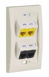
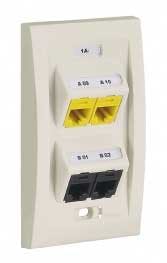
The photograph (above) shows a faceplate on which all labels are positioned adjacent to, centered, and parallel to the port they are identifying. This example includes a flush cover surface adjacent to the faceplate surface that protects the environmentally resistant label material. To comply with the "printed or generated by a mechanical device" requirement, labels are printed with a handheld thermal transfer printer. Labels generated by tabletop laser or inkjet printers would also comply with the requirement.
Patch panels and IDC blocks
Section 5.1.2 also states that each patch panel port or section of an IDC block shall be labeled with the "AN" portion of the identifier. You can meet this requirement by labeling a patch panel or IDC block with the A portion of the identifier, and each port (or IDC connector terminal) with the identifier's N portion.
The photograph of the patch panel (above) shows the N identifier over each port with a flush cover that protects the environmentally resistant label material, while the A portion is placed in the panel space. Once again, this example shows labels printed with a handheld thermal transfer printer; labels generated by tabletop printers would also comply with the 606-A "printed or generated by a mechanical device" requirement.
Individual cables
Section 5.1.2 further states that each end of a horizontal cable shall be labeled with the horizontal link identifier within 300 mm (12 inches) of the end of the cable jacket. This requirement includes cables in the TS, at the work area, and at a consolidation point (CP). The horizontal link identifier shall have the FS-AN format described earlier.
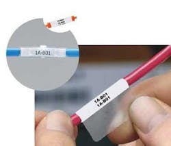
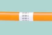
The series of photographs (right) shows: an optical-fiber cable labeled with the horizontal link identifier in the form of a Panduit label that lets users slide or rotate the label for easy viewing; a cable identified with a cable tie that includes a cover, which further protects the environmentally resistant label; and an inkjet-printed, self-laminating wire marker adhered directly to the cable.
Backbone cables
Section 6.1.1 of the standard states that a unique backbone cable identifier shall be assigned to each backbone cable between two TSs in one building. The building-backbone cable identifier shall be marked on each end of the cable within 300 mm (12 inches) of the end of the cable jacket.
The backbone cable shall have the format FS1/FS2-N, where:
- FS1 is the TS identifier for the space containing the termination of one end of the backbone cable;
- FS2 is the TS identifier for the space containing the termination of the other end of the backbone cable;
- N is one or two alphanumeric characters identifying a single cable with one end terminated in the TS designated FS1, and the other end terminated in the TS designated FS2.
Backbone termination points
Section 6.1.2 states that each single copper pair or each single optical fiber in a backbone between two TSs in one building shall be marked on the front of the patch panel, the IDC connector labeling strip, or the optical-fiber patch panel. The identifier (FS1/FS2-N.D) shall be labeled in a way that clearly identifies the associated pair or optical fiber. This requirement may be met by marking the FS1/ FS2-N portion of the identifier on each patch panel, IDC connector, or group of IDC connectors, and the D portion of the identifier by each port or‰ section of an IDC connector terminating the pair or optical fiber.
The FS1/FS2-N.D format breaks down as follows:
- FS1/FS2-N is a building backbone cable identifier;
- D is two to four numeric characters identifying a single copper pair or single optical fiber.
The photo (page 26, bottom) shows the D identifier over each port with a flush cover that protects the environmentally resistant label material. The FS1/FS2-N portion is placed in the panel space.
Each time a cable terminates along the horizontal link back to the TS, the faceplate or outlet and cable that continues that link must be identified in the exact same formats with the exact same legends as outlined earlier in this article.
Grounding busbars
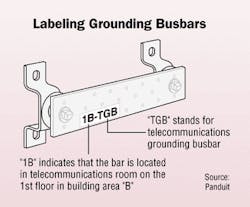
Sections 5.1.3 and 5.1.4 of the standard describe the format for the telecommunications main grounding busbars (TMGB) and other grounding busbars (TGB). Each of these busbars shall be labeled.
The format for the telecommunications main grounding busbar shall be FS-TMGB, while the format for the TGBs shall be FS-TGB.
- FS is the TS identifier for the space containing the busbar;
- TMGB is the portion of an identifier designating a telecommunications main grounding busbar;
- TGB is the portion of the identifier designating a telecommunications grounding busbar.
Each telecommunications space or room shall be assigned an identifier unique within the building. The TS shall be labeled with the TS identifier inside the room so as to be visible to someone working in that room. The TS identifier shall have a format of FS, the elements of which have been described earlier.
Firestop locations
Section 6.1.3 of the standard describes the format for the firestopping location identifier. Each firestopping location shall be labeled at each location where firestopping is installed, on each side of the penetrated fire barrier, within 300 mm (12 inches) of the firestopping material.
The format for the firestopping location identifier shall be F-FSLN(H), where:
- F is numeric character(s) identifying the floor of the building occupied by the TS;
- FSL is an identifier referring to a firestopping location;
- N is two to four numeric characters identifying one firestopping location;
- H is one numeric character specifying the hour rating of the firestopping system.
These explanations and visual examples should provide the fundamental information you need to label your entire network.
This article did not address larger systems, such as campus or multi-campus, or the details of record keeping. But it can help you establish a solid foundation of what is required to label your TIA/EIA-606A-compliant system.
David Morrison is manager of Panduit's Identification Products Division. Note: All connecting-hardware and labeling devices pictured in this article are Panduit Ultimate ID Network Labeling System products (www.panduitncg.com/whatsnew/ultimateIDPressRelease.asp).
Classes of administration
The most important change from the 606 to 606-A standard is the establishment of classes of adminstration. In short, the standard is broken down into four classes of complexity. For instance, a Class 1 system has fewer than 100 users and utilizes a single telecommunications room. A Class 2 system has hundreds of users and will have multiple telecommunications rooms in a single building. A Class 3 system will accommodate 1,000+ users in a campus environment, where you may have multiple buildings with multiple floors in each. A Class 4 system includes thousands of users in a telecommunications infrastructure that extends across multiple geographic locations. In this case, you might have multiple campus locations connected over large geographic distances.
The key is to choose the system that best fits the "future" of your installation. If you are currently a Class 1 infrastructure, but know that this system will eventually expand to a Class 2 administrative system, you should choose to manage the installation under the guidelines of a Class 2 system.
The beauty and simplicity of the new standard for labeling is that it is modular and expandable. If you change from a Class 2 to a Class 3 system, there is no need to go back and re-label all of your connections and terminations.
By using the 606-A standard, installations are organized and recorded, making moves, adds, and changes easier and more efficient.
Todd Fries is HellermannTyton's marketing manager/Identification Systems. The company (www.hellerman.tyton.com) is a global manufacturer of identificaton and network cabling solutions.
